![]()
[Jul 18, 2025] Genuine D-PST-MN-A-24 Exam Dumps Free Demo
Printable & Easy to Use Storage Administrator D-PST-MN-A-24 Dumps 100% Same Q&A In Your Real Exam
NEW QUESTION # 27
Refer to the exhibit.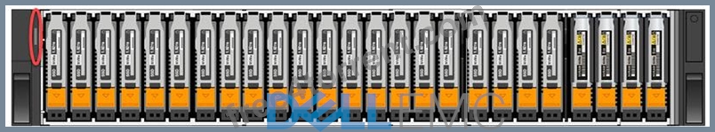
What is indicated when the circled LED on the base enclosure is illuminated amber?
- A. Cluster service mode
- B. Base enclosure power-on
- C. Base enclosure fault
- D. Cluster discovery state
Answer: C
Explanation:
When the circled LED on the base enclosure of a Dell PowerStore system is illuminated amber, it typically indicates a fault within the base enclosure. This could be related to various issues such as power supply problems, cooling system malfunctions, or other operational faults that may affect the enclosure's performance.
In Dell PowerStore systems, LED indicators are used to communicate the status of the system's hardware components. An amber LED specifically suggests that there is a problem that needs to be addressed. The steps to investigate and resolve the issue usually include:
Checking the PowerStore Manager for alerts or messages that provide more details about the fault.
Inspecting the physical hardware to identify any visible signs of damage or failure.
Consulting the Dell PowerStore Hardware Guide for information on LED indicators and their meanings.
Following the recommended actions provided in the guide, which may include checking power connections, ensuring proper airflow, or other hardware checks.
If necessary, contacting Dell Support for further assistance, providing them with the details of the fault LED and any other relevant information observed.
It's important to address any faults indicated by an amber LED promptly to maintain the integrity and reliability of the storage system. The Dell PowerStore documentation provides comprehensive information on LED indicators and troubleshooting steps to help resolve such issues effectively.
NEW QUESTION # 28
Through which network do external hosts connect to the cluster for data access?
- A. Storage
- B. Management
- C. Service
- D. Internal
Answer: A
Explanation:
External hosts connect to the Dell EMC PowerStore cluster for data access through the Storage network.
The Storage network is designed to handle the data traffic between the PowerStore system and the external hosts.
For optimal performance and availability, it is recommended to configure dual redundant fabrics in Fibre Channel configurations, ensuring that each PowerStore node and each external host have connectivity on each of the fabrics12.
This setup minimizes the number of hops between the host and PowerStore, which is crucial for maintaining high-speed data access and reducing latency12.
The Management network, on the other hand, is used for managing and configuring the PowerStore system, not for data access3.
The Service network is typically used for service tasks and is not intended for regular data access by external hosts3.
The Internal network is used for communication within the PowerStore cluster itself and is not accessible by external hosts.
For more detailed information on network considerations and best practices for Dell EMC PowerStore, you can refer to the Dell PowerStore: Best Practices Guide4.
NEW QUESTION # 29
From where can a data collection be initialized within Dell EMC PowerStore Manager?
- A. Cluster, appliance, and alerts
- B. Node, storage resource, and alerts
- C. Cluster, appliance, and event log
- D. Appliance, node, and storage resource
Answer: A
Explanation:
A data collection in Dell EMC PowerStore Manager can be initiated from the cluster, appliance, and alerts sections within the PowerStore Manager user interface. This process is essential for gathering system logs and other information that can be used for troubleshooting or analysis.
To initiate a data collection, follow these steps:
Log into the PowerStore Manager user interface.
Navigate to the 'Settings' menu.
Go to the 'Support' section.
Select 'Gather Support Materials'.
Choose the scope of the data collection, which can be at the cluster level, for a specific appliance, or related to certain alerts.
Click the 'Gather Support Materials' button to start the collection process.
Monitor the progress in the 'Jobs' section of PowerStore Manager or within the 'Support Materials' section1.
It is important to note that the data collection process may take some time to complete, depending on the amount of data and the system's performance. Once the data collection is finished, the gathered materials can be used by Dell EMC support for further analysis or can be reviewed by the storage administrator to address any issues1. For more detailed instructions on data collection, refer to the Dell EMC PowerStore documentation or the support knowledge base articles provided by Dell23. Following these guidelines ensures that the data is collected correctly and efficiently.
NEW QUESTION # 30
Refer to the exhibit.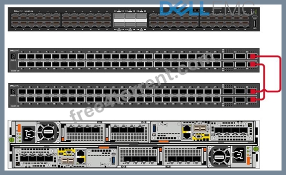
Refer to the exhibit.
What Dell EMC PowerStore ToR front-end cabling is shown?
- A. Core switch uplink
- B. Management and discovery
- C. VLT interconnectivity
- D. OOB Management
Answer: C
NEW QUESTION # 31
What is the protocol used for the storage network?
- A. FC
- B. SMB
- C. NFS
- D. iSCSI
Answer: A
Explanation:
The protocol used for the storage network in Dell PowerStore systems is Fibre Channel (FC). FC is a high-speed network technology primarily used for storage networking. Dell PowerStore utilizes FC as part of its all-NVMe design, which also includes NVMe-over-fabric networking to deliver low latency performance for storage workloads1.
Fibre Channel provides several benefits for storage networks, including:
High throughput and low latency for storage operations.
Support for long-distance networking, which is beneficial for disaster recovery and remote backups.
A mature and widely supported ecosystem with a variety of hardware and software options.
For detailed information on configuring and using FC with Dell PowerStore, administrators should refer to the Dell PowerStore Networking Guide for Storage Services and the Dell PowerStore Best Practices Guide. These documents provide comprehensive instructions on network configurations, including best practices for setting up and managing FC networks within Dell PowerStore environments23. Following these guidelines ensures optimal performance and reliability of the storage network.
NEW QUESTION # 32
What is the default log collection schedule?
- A. Weekly
- B. As scheduled during install
- C. Hourly
- D. Daily
Answer: A
Explanation:
The default log collection schedule for Dell PowerStore is set to a weekly basis. This schedule is designed to balance the need for regular monitoring with the storage and processing considerations of collecting logs. Collecting logs on a weekly basis provides a sufficient overview of the system's performance and any potential issues that may arise, without overwhelming the system administrators with too much data.
The log collection process includes gathering various logs that may be required for troubleshooting PowerStore issues, such as Support Materials, Performance Metrics Archives, Dump Files, and others. The process can be initiated through the PowerStore Manager user interface or using the CLI in an SSH session1.
For more detailed information on log collection schedules and procedures, administrators should refer to the official Dell PowerStore documentation, which provides comprehensive instructions on how to generate, collect, and manage logs for effective system maintenance and troubleshooting1.
NEW QUESTION # 33
A Storage Administrator needs to connect through SSH to run svc commands. How is the SSH session configured?
- A. Appliance IP address using port 26
- B. NAS server IP address using port 22
- C. NAS server IP address using port 26
- D. Appliance IP address using port 22
Answer: D
Explanation:
The SSH session for a Storage Administrator to run svc commands on a Dell EMC PowerStore system is configured using the Appliance IP address using port 22.
To connect to the service console over SSH, the Storage Administrator should use the appliance IP address.
The default SSH port for accessing the service console is port 221.
SSH access to the nodes may be required for troubleshooting and is not enabled by default. To enable SSH access:
Navigate to Settings.
Select SSH Management from the Security section.
Choose the appliance or appliances on which to enable SSH.
Click ENABLE SSH1.
The service user account is used for SSH login, and the password is set during the Initial Configuration Wizard (ICW) or can be reset from the PowerStore Manager user interface1.
It's important to note that the SSH port used to log in to the service container is port 22 after the cluster creation is completed. Before the ICW is run, port 26 may be used1.
For detailed instructions on how to connect to the service console over SSH, please refer to the official Dell documentation or contact Dell Support for assistance.
NEW QUESTION # 34
How can the PUHC health check results be viewed?
- A. From syslog server
- B. From management DB
- C. By accessing the Swagger UI
- D. In Details of Appliances and Nodes
Answer: D
Explanation:
The Pre-Upgrade Health Check (PUHC) results for a Dell EMC PowerStore system can be viewed in the details of Appliances and Nodes within the PowerStore Manager (UI). The PUHC is designed to validate the health of the cluster before a software upgrade and is more thorough than the continuous background checks performed by the alert mechanism of PowerStore1.
To view the PUHC health check results, follow these steps:
Log in to the PowerStore Manager using a supported web browser.
Navigate to the 'Settings' menu and select 'Upgrades'.
Within the 'Upgrades' section, you can view the status and results of the PUHC.
Click on the details of a specific appliance or node to see the health check results, including any warnings or actions required.
It is important to address any issues highlighted by the PUHC before proceeding with a software upgrade to ensure a successful update process. For more detailed instructions on running and interpreting the PUHC, refer to the Dell Support Knowledge Base Article1. This resource provides comprehensive guidance on using the PUHC and System Checks to prepare for a Non-Disruptive Upgrade (NDU).
NEW QUESTION # 35
While on-site installing a Dell EMC PowerStore T system, the node A embedded module management Ethernet port link LED is off. What does this indicate?
- A. Network connection is established
- B. Port speed is 1 GB/S
- C. Port speed is 10 GB/s
- D. No network connection is established
Answer: D
Explanation:
When the link LED of the node A embedded module management Ethernet port is off, it indicates that there is no network connection established. The link LED is typically used to indicate the presence of a network connection and its status. If the LED is off, it means that the Ethernet port is not currently connected to a network or there is an issue preventing the connection from being established1.
In the case of the Dell EMC PowerStore T system, the embedded module management Ethernet ports are used for network management traffic. It is essential that these ports have an active network connection for the system to be managed remotely. If the link LED is off, the following steps should be taken:
Check the physical connection of the Ethernet cable to ensure it is securely plugged into both the node's port and the corresponding switch or router port.
Verify that the switch or router is powered on and functioning correctly.
Ensure that the correct port on the switch or router is being used and that it is configured correctly for the PowerStore system.
If the issue persists after checking the physical connections and switch/router configuration, consult the Dell EMC PowerStore T Installation and Service Manual for further troubleshooting steps2.
It is important to resolve any network connection issues promptly to maintain the manageability and accessibility of the PowerStore system. Following the official Dell documentation and support resources will help ensure that the system is installed and configured correctly for optimal performance and reliability.
NEW QUESTION # 36
Under which condition does the Dell EMC PowerStore equipment in the rack require additional stability?
- A. Unstable humidity
- B. High temperatures
- C. Low temperatures
- D. When shipping the system
Answer: D
Explanation:
When shipping the system, additional stability is necessary to ensure that the equipment remains secure and undamaged during transportation. Proper stabilization prevents any potential movement or impact that could harm the delicate components of the system.
NEW QUESTION # 37
What describes the SAS cabling when adding an expansion enclosure to a Dell EMC PowerStore, for each node and expansion enclosure side?
- A. SAS cabling goes from existing B ports to new A ports.
At the last enclosure, SAS cabling returns from the B ports to the alternate node's A ports. - B. SAS cabling goes from existing A ports to new B ports.
At the last enclosure, SAS cabling returns from the A ports to the alternate node's B ports. - C. SAS cabling goes from existing A ports to new B ports.
At the last enclosure, SAS cabling returns from the A ports to the originating node's B ports. - D. SAS cabling goes from existing B ports to new A ports.
At the last enclosure, SAS cabling returns from the B ports to the originating node's A ports.
Answer: B
Explanation:
The correct description of the SAS cabling when adding an expansion enclosure to a Dell EMC PowerStore, for each node and expansion enclosure side, is Option D: SAS cabling goes from existing A ports to new B ports. At the last enclosure, SAS cabling returns from the A ports to the alternate node's B ports.
When adding a SAS expansion enclosure to a Dell EMC PowerStore system, the cabling must be done in a specific manner to ensure proper connectivity and performance.
The SAS cabling should start from the existing A ports on the base enclosure and connect to the new B ports on the expansion enclosure1.
At the last expansion enclosure in the chain, the SAS cabling should return from the A ports back to the B ports on the alternate node1.
This cabling method ensures that each node is connected to each expansion enclosure and that the enclosures are daisy-chained correctly for optimal performance and redundancy1.
For detailed cabling instructions and diagrams, it is recommended to consult the Dell PowerStore Installation and Service Guide or contact Dell EMC support for assistance.
NEW QUESTION # 38
Refer to the Exhibit.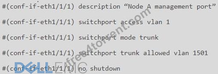
What is the result of the network configuration shown for a Dell EMC PowerStore T node A management port?
- A. VLAN 1 passes untagged traffic, VLAN 1501 passes tagged traffic
- B. VLAN 1 and VLAN 1501 pass tagged traffic
- C. VLAN 1 and VLAN 1501 pass untagged traffic
- D. VLAN 1 passes tagged traffic, VLAN 1501 passes untagged traffic
Answer: A
Explanation:
The network configuration shown for a Dell EMC PowerStore T node A management port indicates that VLAN 1 is set as the access VLAN, which means it will pass untagged traffic. The port is also configured as a trunk port, which allows it to pass traffic from multiple VLANs, but only VLAN 1501 is specified in the allowed list, meaning it will pass as tagged traffic. This configuration is typical for network interfaces on storage systems where management traffic is separated from other types of traffic for security and performance reasons.
In detail, the configuration commands are:
switchport access vlan 1: Sets VLAN 1 as the access VLAN, which passes untagged traffic.
switchport mode trunk: Enables trunking on the port, allowing it to pass traffic from multiple VLANs.
switchport trunk allowed vlan 1501: Specifies that only VLAN 1501 traffic is allowed on the trunk and will be tagged.
NEW QUESTION # 39
What describes Dell EMC PowerStore X front-end cabling?
- A. Uses VLTi data switch interconnectivity to support vMotion networks
- B. Uses internal VMware virtual switching and does not require a management network
- C. Management and discovery use the same cables and connections as storage
- D. Storage and management use the same LACP bonded cable connection
Answer: C
Explanation:
The Dell EMC PowerStore X series supports Ethernet connectivity through ports on the embedded module, and on optional I/O modules1. This design allows for management and discovery to use the same cables and connections as storage. The PowerStore X models support front-end NVMe connectivity with NVMe over Fibre Channel and NVMe over TCP, providing a complete end-to-end NVMe solution2.
For the PowerStore X, the management network is integrated with the storage network, which simplifies the cabling requirements and reduces the number of separate networks that need to be maintained. This integration is particularly beneficial in VMware environments where the PowerStore X can leverage internal VMware virtual switching, which further streamlines the network infrastructure1.
In summary, the front-end cabling of the Dell EMC PowerStore X is designed to consolidate management and storage networking, which simplifies the overall network design and reduces the complexity of cable management. This approach is aligned with best practices for storage connectivity and ensures efficient use of network resources3.
NEW QUESTION # 40
What are the recommended number of network switches in a Dell EMC PowerStore T environment?
- A. 0
- B. 1
- C. 2
- D. 3
Answer: A
Explanation:
In a Dell EMC PowerStore T environment, the recommended number of network switches is two1. This recommendation is based on best practices for general network performance and high availability. Using two switches allows for redundancy and ensures that if one switch fails, the other can continue to handle the network traffic without interruption1.
The use of multiple switches connected with technologies like Virtual Link Trunking (VLT) and Link Aggregation Control Protocol (LACP) or their equivalents is advised. Each PowerStore node should have connectivity to all linked switches to maintain high availability and optimal network performance1.
For detailed network design and switch configuration recommendations, administrators should refer to the Dell PowerStore Networking Guide for PowerStore T Models and other official Dell documentation2. These resources provide comprehensive guidelines on setting up the network infrastructure to support PowerStore T systems effectively.
NEW QUESTION # 41
Which reference source provides service information and FRU procedures for Dell EMC PowerStore?
- A. PowerStore Manager help
- B. DELL EMC PowerStore Product Page
- C. DELL EMC Online Support
- D. SolVe Tool
Answer: D
Explanation:
The SolVe Tool is the reference source that provides service information and Field Replaceable Unit (FRU) procedures for Dell EMC PowerStore. The SolVe Tool is an online resource that offers step-by-step guidance for various procedures, including servicing and replacing hardware components, also known as FRUs1.
The tool is designed to help users and service technicians perform maintenance tasks accurately and efficiently. It includes detailed instructions, diagrams, and other helpful information that can assist in troubleshooting and resolving issues with Dell EMC PowerStore systems.
For accessing the SolVe Tool and finding the service information and FRU procedures for PowerStore, users can visit the Dell Support website and navigate to the SolVe Online section. Additionally, the PowerStore Info Hub provides a collection of product documentation and videos that can be useful for understanding the system's operation and maintenance2.
It is important to use the SolVe Tool and follow the provided instructions carefully to ensure that any service actions are performed correctly and safely, maintaining the integrity and performance of the PowerStore system.
NEW QUESTION # 42
What is the maximum number of expansion enclosures that a single Dell EMC PowerStore 9000T appliance supports?
- A. 0
- B. 1
- C. 2
- D. 3
Answer: B
Explanation:
The maximum number of expansion enclosures that a single Dell EMC PowerStore 9000T appliance supports is three. This is consistent with the design and specifications provided by Dell for the PowerStore series, which allows for scalability within the storage environment1.
The expansion enclosures are used to increase the storage capacity of the PowerStore system beyond what is available in the base enclosure. Each expansion enclosure connects to the base appliance and adds additional drive slots for storage expansion.
For detailed information on the configuration and limitations of expansion enclosures for the PowerStore 9000T model, administrators should refer to the official Dell PowerStore Hardware Information Guide and the Dell PowerStore Technical Primer. These documents provide comprehensive guidelines on the physical and logical expansion capabilities of the PowerStore systems23. Adhering to these specifications is crucial to ensure proper system performance and to avoid unsupported configurations.
NEW QUESTION # 43
How is a defective embedded module displayed in Dell EMC PowerStore Manager?
- A. Orange with an empty state
- B. Blue with an empty state
- C. Orange with a faulted state
- D. Blue with a faulted state
Answer: C
Explanation:
In Dell EMC PowerStore Manager, a defective embedded module is displayed as orange with a faulted state. This color coding is used to indicate that there is a fault with the embedded module. The PowerStore Manager provides a visual representation of the system's health and status, and the color orange is typically associated with a warning or an issue that needs attention.
The procedure for identifying and replacing a faulted embedded module involves using the PowerStore Manager to locate the faulted component. Once identified, the module displays an orange LED to indicate its faulted state. This is part of the system's design to help administrators quickly and easily identify components that require attention1.
For detailed instructions on replacing a faulted embedded module or understanding the LED states for troubleshooting, you can refer to the PowerStore documentation provided by Dell, which includes comprehensive guides on handling such scenarios2.
NEW QUESTION # 44
Which component is only replaceable by qualified personnel?
- A. Base enclosure
- B. Memory module
- C. Power supply
- D. Embedded I/O module
Answer: A
Explanation:
The base enclosure is a component that is typically only replaceable by qualified personnel. This is because the base enclosure of a Dell PowerStore system contains critical components and connections that require specialized knowledge and tools to handle properly. Replacing a base enclosure involves understanding the system's architecture, safely disconnecting and reconnecting various components, and ensuring that the system is not compromised during the process.
The memory module, embedded I/O module, and power supply are designed to be more accessible for replacement and may fall under the category of customer-replaceable units (CRUs) or field-replaceable units (FRUs), depending on the specific model and configuration of the PowerStore system1.
For detailed procedures on replacing the base enclosure or any other components, it is recommended to refer to the official Dell PowerStore Installation and Service Guide. This guide provides step-by-step instructions and safety precautions for qualified personnel to follow when performing hardware replacements1. It is crucial to adhere to these guidelines to maintain system integrity and ensure that the storage system continues to operate effectively after the replacement.
NEW QUESTION # 45
A Storage Administrator notices two fans in a Dell EMC PowerStore are faulted. What describes the system behavior in this circumstance?
- A. CPU clock speed is reduced by 50% to lower internal temperatures and the system continues normal operations
- B. A five-minute timer starts upon the second fan fault and the system shuts down automatically after the timer expires
- C. Upon the second fan fault, all host I/O is terminated immediately and the PowerStore goes through the halt and vault process and shuts down
- D. An increased fan speed signal is sent to the surviving fans and the system continues normal operations
Answer: D
Explanation:
When two fans in a Dell EMC PowerStore system are faulted, the system's behavior is to send an increased fan speed signal to the surviving fans to compensate for the loss and continue normal operations. This is a part of the system's design to ensure redundancy and maintain cooling within operational parameters even when one or more fans are not functioning1.
The system monitors the health of all fans continuously. If a fan fault is detected, the system will:
Generate an alert to notify the administrator of the fault.
Increase the speed of the remaining fans to prevent overheating.
Continue to operate normally unless the temperature exceeds safe operating limits.
The administrator should then take the following steps:
Acknowledge the alert in the PowerStore Manager.
Plan for the replacement of the faulted fans as soon as possible to restore full redundancy.
Follow the replacement procedures as outlined in the Dell PowerStore Installation and Service Guide2.
It is important to address fan faults promptly to ensure the long-term health and performance of the PowerStore system. The increased fan speed is a temporary measure to maintain operations until the faulted fans can be replaced.
NEW QUESTION # 46
What is a step in configuring the ToR data switches for a Dell EMC PowerStore T?
- A. Configure ports for management on native VLAN
- B. Create VLANs for NAS server networks
- C. Configure a port for the discovery laptop
- D. Create VLAN for vMotion networks
Answer: C
Explanation:
Configuring the Top of Rack (ToR) data switches for a Dell EMC PowerStore T involves several steps to ensure proper network setup and connectivity. One of the essential steps is to configure a port for the discovery laptop. This step is necessary for the initial discovery and configuration of the PowerStore appliances.
The process typically includes:
Identifying an unused port on the ToR switch that will be dedicated to the discovery laptop.
Configuring the identified port with the appropriate VLAN settings that match the network design of the PowerStore environment.
Ensuring that the port has the correct speed and duplex settings to communicate effectively with the discovery laptop.
Connecting the discovery laptop to the configured port to begin the discovery process of the PowerStore appliances.
This step is crucial as the discovery laptop is used to run the PowerStore Discovery Utility, which helps in identifying PowerStore appliances on the network and assists with the initial configuration1. For detailed instructions on configuring ToR switches and other networking components for PowerStore T, refer to the Dell PowerStore Networking Guide for PowerStore T Models2.
NEW QUESTION # 47
......
EMC D-PST-MN-A-24 Exam Syllabus Topics:
| Topic | Details |
|---|---|
| Topic 1 |
|
| Topic 2 |
|
| Topic 3 |
|
| Topic 4 |
|
D-PST-MN-A-24 Practice Test Give You First Time Success with 100% Money Back Guarantee!: https://validdumps.free4torrent.com/D-PST-MN-A-24-valid-dumps-torrent.html