![]()
Oct-2024 Pass EMC D-PST-MN-A-24 Exam in First Attempt Easily
Free D-PST-MN-A-24 Exam Files Downloaded Instantly 100% Dumps & Practice Exam
EMC D-PST-MN-A-24 Exam Syllabus Topics:
| Topic | Details |
|---|---|
| Topic 1 |
|
| Topic 2 |
|
| Topic 3 |
|
NEW QUESTION # 28
What does the output of the command "svc_diag list -- basic" show?
- A. Failover status
- B. Service tag
- C. License status
- D. Boot mode
Answer: B
Explanation:
The output of the command "svc_diag list - basic" on a Dell PowerStore system typically shows service tag information.
The "svc_diag" command is part of the service scripts provided by Dell for diagnostic purposes on PowerStore systems.
The "list" option with the "-basic" flag is used to display a list of basic system information, which usually includes the service tag, among other details.
The service tag is a unique identifier for Dell products that is used for various purposes, including support and maintenance.
While the exact output of the command can vary based on the software version and specific system configuration, the service tag is a common piece of information displayed by such diagnostic commands1.
For the most accurate and up-to-date information about the "svc_diag list - basic" command and its output, it is recommended to consult the Dell PowerStore Service Scripts Guide or contact Dell Support directly.
NEW QUESTION # 29
A Storage Administrator notices two fans in a Dell EMC PowerStore are faulted. What describes the system behavior in this circumstance?
- A. An increased fan speed signal is sent to the surviving fans and the system continues normal operations
- B. CPU clock speed is reduced by 50% to lower internal temperatures and the system continues normal operations
- C. A five-minute timer starts upon the second fan fault and the system shuts down automatically after the timer expires
- D. Upon the second fan fault, all host I/O is terminated immediately and the PowerStore goes through the halt and vault process and shuts down
Answer: A
Explanation:
When two fans in a Dell EMC PowerStore system are faulted, the system's behavior is to send an increased fan speed signal to the surviving fans to compensate for the loss and continue normal operations. This is a part of the system's design to ensure redundancy and maintain cooling within operational parameters even when one or more fans are not functioning1.
The system monitors the health of all fans continuously. If a fan fault is detected, the system will:
Generate an alert to notify the administrator of the fault.
Increase the speed of the remaining fans to prevent overheating.
Continue to operate normally unless the temperature exceeds safe operating limits.
The administrator should then take the following steps:
Acknowledge the alert in the PowerStore Manager.
Plan for the replacement of the faulted fans as soon as possible to restore full redundancy.
Follow the replacement procedures as outlined in the Dell PowerStore Installation and Service Guide2.
It is important to address fan faults promptly to ensure the long-term health and performance of the PowerStore system. The increased fan speed is a temporary measure to maintain operations until the faulted fans can be replaced.
NEW QUESTION # 30
A Storage Administrator needs to address specific fixes within their Dell EMC PowerStore system. Which NDU software upgrade option is used for this situation?
- A. Software releases
- B. Drive firmware
- C. vCenter
- D. Hotfixes
Answer: D
Explanation:
In the context of Dell EMC PowerStore, when a Storage Administrator needs to address specific fixes within their system, the appropriate Non-Disruptive Upgrade (NDU) software upgrade option to use is Hotfixes. Hotfixes are targeted software updates that address specific issues or bugs within the system without requiring a full software release upgrade1.
The process for applying hotfixes typically involves:
Identifying the specific issue and the corresponding hotfix that addresses it.
Downloading the hotfix from the Dell Support website or through the PowerStore Manager interface.
Applying the hotfix to the PowerStore system using the NDU process, which ensures that the system remains operational and accessible during the upgrade.
Verifying that the hotfix has been applied successfully and that the issue has been resolved.
It is important to follow the detailed instructions provided in the Dell PowerStore Software Upgrade Guide when applying hotfixes. This guide outlines the steps for preparing for an NDU, including any preliminary checks and concluding checks to ensure the integrity of the upgrade process2.
Administrators should also consult the PowerStore Release Notes to determine which software upgrade packages, including hotfixes, are required for their specific PowerStore model and configuration2. Adhering to these guidelines helps ensure that the system is updated correctly and that the specific fixes are applied effectively.
NEW QUESTION # 31
While on-site installing a Dell EMC PowerStore system, the node A and B embedded module fault LEDs are alternating blue and amber (blue for 3 seconds). What does this indicate?
- A. Nodes are in service mode
- B. The system is not initialized
- C. The system is booting
- D. Nodes are in degraded mode
Answer: B
Explanation:
When the node A and B embedded module fault LEDs on a Dell EMC PowerStore system are alternating between blue and amber, with the blue LED illuminated for 3 seconds, it indicates that the system is not initialized1. This LED behavior is part of the system's design to communicate its current state to the user or technician on-site.
The initialization process is a critical step during the installation of a PowerStore system. It involves setting up the system's configuration, including network settings, storage pools, and other essential parameters. Until this process is completed, the system cannot perform storage operations or host any virtual machines.
To resolve this and initialize the system, the following steps should be taken:
Connect to the system through the PowerStore Manager using a supported web browser.
Complete the Initial Configuration Wizard (ICW), which guides you through the necessary steps to initialize the system.
Once the ICW is completed, the system will finalize its configuration and the LEDs should reflect a normal operational state.
For more detailed guidance on the initialization process and understanding the LED indicators, refer to the Dell PowerStore Installation and Service Guide2. This document provides comprehensive instructions on installing and configuring the PowerStore system, ensuring it is ready for use.
NEW QUESTION # 32
In which step of the ICW can the configuration details be exported?
- A. License Configuration
- B. Cluster Details
- C. Support Assist
- D. Cluster Configuration
Answer: D
Explanation:
The configuration details can be exported during the Cluster Configuration step of the Initial Configuration Wizard (ICW) for Dell PowerStore. This step allows the user to review the chosen configuration information, validate the configuration, and initiate the cluster creation. It is at this point that the option to export the configuration details is provided1.
For a detailed guide on how to navigate the ICW and export configuration details, users should refer to the official Dell PowerStore Manager Overview documentation or the PowerStore Info Hub, which includes product documentation and videos that assist with PowerStore deployment and maintenance12. It is important to follow the official documentation to ensure that the process is carried out correctly and to maintain system integrity and compliance with warranty and support agreements.
NEW QUESTION # 33
Refer to the Exhibit.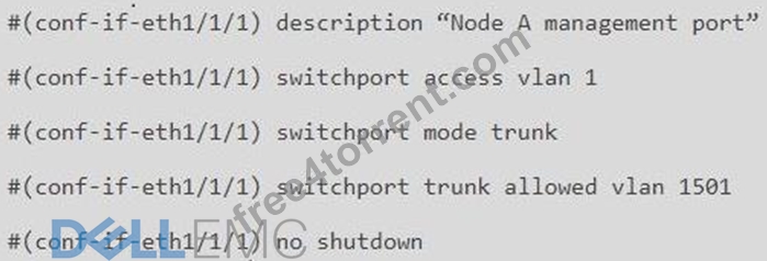
What is the result of the network configuration shown for a Dell EMC PowerStore T node A management port?
- A. VLAN 1 and VLAN 1501 pass untagged traffic
- B. VLAN 1 and VLAN 1501 pass tagged traffic
- C. VLAN 1 passes tagged traffic, VLAN 1501 passes untagged traffic
- D. VLAN 1 passes untagged traffic, VLAN 1501 passes tagged traffic
Answer: D
Explanation:
The network configuration shown for a Dell EMC PowerStore T node A management port indicates that VLAN 1 is set as the access VLAN, which means it will pass untagged traffic. The port is also configured as a trunk port, which allows it to pass traffic from multiple VLANs, but only VLAN 1501 is specified in the allowed list, meaning it will pass as tagged traffic. This configuration is typical for network interfaces on storage systems where management traffic is separated from other types of traffic for security and performance reasons.
In detail, the configuration commands are:
switchport access vlan 1: Sets VLAN 1 as the access VLAN, which passes untagged traffic.
switchport mode trunk: Enables trunking on the port, allowing it to pass traffic from multiple VLANs.
switchport trunk allowed vlan 1501: Specifies that only VLAN 1501 traffic is allowed on the trunk and will be tagged.
NEW QUESTION # 34
Refer to the exhibit.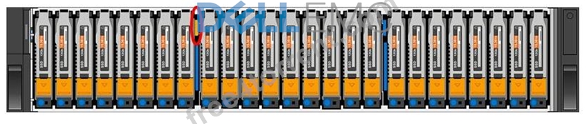
What is indicated when the circled LED on an expansion enclosure is illuminated amber?
- A. SAS bus link down
- B. Expansion enclosure power-on
- C. Expansion enclosure faulted
- D. SAS bus link up
Answer: C
Explanation:
The illuminated amber LED on an expansion enclosure typically indicates a fault. In the context of Dell PowerStore expansion enclosures, an amber light can signify various issues such as power supply problems, cooling system malfunctions, or other operational faults that may affect the enclosure's performance.
When troubleshooting, the following steps are generally taken:
Identify the specific LED that is illuminated amber using the hardware documentation.
Consult the Dell PowerStore Hardware Guide to determine the exact nature of the fault indicated by the amber LED.
Follow the recommended actions provided in the guide, which may include checking power connections, ensuring proper airflow, or other hardware checks.
If the issue persists, contact Dell Support for further assistance, providing them with the details of the fault LED and any other relevant information observed.
It's important to address any faults indicated by an amber LED promptly to maintain the integrity and reliability of the storage system. The Dell PowerStore documentation provides comprehensive information on LED indicators and troubleshooting steps to help resolve such issues effectively.
NEW QUESTION # 35
A Storage Administrator has an existing single appliance Dell EMC PowerStore 3000T cluster. An additional PowerStore 9000T has been purchased to add into the existing cluster.
How does the administrator proceed?
- A. Remove two of the four NVMe NVRAM drives from the 9000T; the caching configuration of all clustered appliances must match
- B. The new appliance cannot be added to the cluster; appliance model and type must match when clustering appliances together
- C. Additional VLT links on the ToR switching must be configured for the 9000T to support the increased inter-switch network load
- D. Add the new 9000T appliance into the cluster per the procedure; mixed models of the same type are supported
Answer: D
Explanation:
The correct procedure for a Storage Administrator to add a new PowerStore 9000T appliance into an existing single appliance Dell EMC PowerStore 3000T cluster is to add the new 9000T appliance into the cluster per the procedure; mixed models of the same type are supported.
Dell PowerStore allows for the addition of appliances to an existing cluster, enabling both scaling up and scaling out.
When adding a new appliance to an existing cluster, it is important to ensure that the appliance is uninitialized and that both the new appliance and the existing cluster are in a healthy state1.
The process of adding an appliance is facilitated through the PowerStore Manager. The administrator should navigate to the Hardware page and click the Add button to present the available unconfigured appliances that can be added1.
It is not necessary to configure additional VLT links on the ToR switching specifically for the 9000T to support the increased inter-switch network load as part of the initial addition process1.
There is no requirement that the appliance model and type must match when clustering appliances together, allowing for mixed models of the same type within a cluster1.
Removing NVMe NVRAM drives from the 9000T is not a standard procedure for clustering and is not required for the caching configuration of all clustered appliances to match1.
For detailed procedures on adding appliances to a Dell EMC PowerStore cluster, it is recommended to refer to the official Dell PowerStore Clustering and High Availability documentation or contact Dell EMC support for guidance.
NEW QUESTION # 36
What safety equipment is critical to have on hand to avoid equipment failure before replacing any components in a Dell EMC PowerStore array?
- A. Rail Kit
- B. ESD Kit
- C. Maintenance Kit
- D. Stabilization Kit
Answer: B
Explanation:
When replacing any components in a Dell EMC PowerStore array, it is critical to have an Electrostatic Discharge (ESD) Kit on hand to avoid equipment failure. The ESD Kit typically includes tools like wristbands and gloves that help prevent static electricity from damaging the electronic components during the replacement process.
Before beginning any maintenance work on the PowerStore array, it is essential to:
Use the ESD wristband by attaching one end to your wrist and connecting the other end to a grounded object.
Wear ESD gloves to handle sensitive components.
Ensure that the work area is free from static-prone materials and conditions.
Follow the detailed safety precautions and procedures outlined in the PowerStore Installation and Service Guide1.
Using an ESD Kit is a standard safety practice in the maintenance of electronic equipment, as static electricity can cause irreparable damage to sensitive components. The Dell PowerStore Installation and Service Guide provides comprehensive safety instructions, including the use of ESD protection, to ensure the safe handling of replaceable units2.
NEW QUESTION # 37
A Storage Administrator needs to connect through SSH to run svc commands. How is the SSH session configured?
- A. Appliance IP address using port 26
- B. Appliance IP address using port 22
- C. NAS server IP address using port 26
- D. NAS server IP address using port 22
Answer: B
Explanation:
The SSH session for a Storage Administrator to run svc commands on a Dell EMC PowerStore system is configured using the Appliance IP address using port 22.
To connect to the service console over SSH, the Storage Administrator should use the appliance IP address.
The default SSH port for accessing the service console is port 221.
SSH access to the nodes may be required for troubleshooting and is not enabled by default. To enable SSH access:
Navigate to Settings.
Select SSH Management from the Security section.
Choose the appliance or appliances on which to enable SSH.
Click ENABLE SSH1.
The service user account is used for SSH login, and the password is set during the Initial Configuration Wizard (ICW) or can be reset from the PowerStore Manager user interface1.
It's important to note that the SSH port used to log in to the service container is port 22 after the cluster creation is completed. Before the ICW is run, port 26 may be used1.
For detailed instructions on how to connect to the service console over SSH, please refer to the official Dell documentation or contact Dell Support for assistance.
NEW QUESTION # 38
Refer to the exhibit.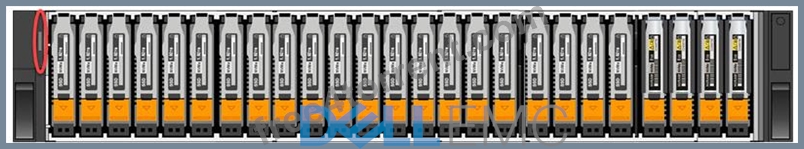
What is indicated when the circled LED on the base enclosure is illuminated amber?
- A. Base enclosure power-on
- B. Base enclosure fault
- C. Cluster discovery state
- D. Cluster service mode
Answer: B
Explanation:
When the circled LED on the base enclosure of a Dell PowerStore system is illuminated amber, it typically indicates a fault within the base enclosure. This could be related to various issues such as power supply problems, cooling system malfunctions, or other operational faults that may affect the enclosure's performance.
In Dell PowerStore systems, LED indicators are used to communicate the status of the system's hardware components. An amber LED specifically suggests that there is a problem that needs to be addressed. The steps to investigate and resolve the issue usually include:
Checking the PowerStore Manager for alerts or messages that provide more details about the fault.
Inspecting the physical hardware to identify any visible signs of damage or failure.
Consulting the Dell PowerStore Hardware Guide for information on LED indicators and their meanings.
Following the recommended actions provided in the guide, which may include checking power connections, ensuring proper airflow, or other hardware checks.
If necessary, contacting Dell Support for further assistance, providing them with the details of the fault LED and any other relevant information observed.
It's important to address any faults indicated by an amber LED promptly to maintain the integrity and reliability of the storage system. The Dell PowerStore documentation provides comprehensive information on LED indicators and troubleshooting steps to help resolve such issues effectively.
NEW QUESTION # 39
Which component is only replaceable by qualified personnel?
- A. Memory module
- B. Embedded I/O module
- C. Power supply
- D. Base enclosure
Answer: D
Explanation:
The base enclosure is a component that is typically only replaceable by qualified personnel. This is because the base enclosure of a Dell PowerStore system contains critical components and connections that require specialized knowledge and tools to handle properly. Replacing a base enclosure involves understanding the system's architecture, safely disconnecting and reconnecting various components, and ensuring that the system is not compromised during the process.
The memory module, embedded I/O module, and power supply are designed to be more accessible for replacement and may fall under the category of customer-replaceable units (CRUs) or field-replaceable units (FRUs), depending on the specific model and configuration of the PowerStore system1.
For detailed procedures on replacing the base enclosure or any other components, it is recommended to refer to the official Dell PowerStore Installation and Service Guide. This guide provides step-by-step instructions and safety precautions for qualified personnel to follow when performing hardware replacements1. It is crucial to adhere to these guidelines to maintain system integrity and ensure that the storage system continues to operate effectively after the replacement.
NEW QUESTION # 40
When looking at the base enclosure front view, what does a solid amber drive LED indicate?
- A. Rebuild activity
- B. Faulted drive
- C. Normal activity
- D. Discover new drive
Answer: B
Explanation:
When observing the base enclosure front view of a Dell PowerStore system, a solid amber drive LED is an indication of a faulted drive. This LED status is used to alert the storage administrator that there is a fault within the drive that requires attention12.
The LED states for the Dell PowerStore base enclosure are as follows:
Blue: Power is on, and no fault has occurred.
Solid Amber: Power is on, and a fault has occurred within the enclosure.
Blue after Amber Alternating: Power is on, but the system is not initialized.
Off: Power is off.
In the event of a solid amber LED, the recommended steps are:
Identify the faulted drive: Look for the drive with the solid amber LED.
Check the PowerStore Manager: Use the PowerStore Manager to identify the specific error or fault code associated with the drive.
Follow the troubleshooting steps: Refer to the Dell PowerStore Troubleshooting Guide for detailed steps on resolving the issue with the faulted drive.
Replace the drive if necessary: If the drive is determined to be faulty and cannot be recovered, follow the Dell PowerStore Hardware Information Guide for instructions on safely replacing the drive.
For more detailed information and guidance, refer to the official Dell PowerStore documentation, such as the PowerStore Hardware Information Guide and the PowerStore Troubleshooting Guide, or contact Dell support directly
NEW QUESTION # 41
How can the PUHC health check results be viewed?
- A. From syslog server
- B. In Details of Appliances and Nodes
- C. From management DB
- D. By accessing the Swagger UI
Answer: B
Explanation:
The Pre-Upgrade Health Check (PUHC) results for a Dell EMC PowerStore system can be viewed in the details of Appliances and Nodes within the PowerStore Manager (UI). The PUHC is designed to validate the health of the cluster before a software upgrade and is more thorough than the continuous background checks performed by the alert mechanism of PowerStore1.
To view the PUHC health check results, follow these steps:
Log in to the PowerStore Manager using a supported web browser.
Navigate to the 'Settings' menu and select 'Upgrades'.
Within the 'Upgrades' section, you can view the status and results of the PUHC.
Click on the details of a specific appliance or node to see the health check results, including any warnings or actions required.
It is important to address any issues highlighted by the PUHC before proceeding with a software upgrade to ensure a successful update process. For more detailed instructions on running and interpreting the PUHC, refer to the Dell Support Knowledge Base Article1. This resource provides comprehensive guidance on using the PUHC and System Checks to prepare for a Non-Disruptive Upgrade (NDU).
NEW QUESTION # 42
A Storage Administrator needs to add drives to a base enclosure of a Dell EMC PowerStore 3000X system. The system currently contains 10 750-GB NVMe SCM drives.Which drive configuration maximizes the base enclosure capacity?
- A. 13 750-GB NVMe SCM drives in slots 10-22
- B. 13 15360-GB NVMe SSD drives in slots 10-22
- C. 11 750-GB NVMe SCM drives in slots 10-20
- D. 11 15360-GB NVMe SSD drives in slots 10-20
Answer: B
NEW QUESTION # 43
How many nodes are in the base enclosure?
- A. 1 node with duel connectivity
- B. 2 nodes configured as Active-Active
- C. 1 node with high availability enabled
- D. 2 nodes configured as Active-Standby
Answer: D
Explanation:
The Dell EMC PowerStore base enclosure contains two nodes. These nodes are configured in an Active-Standby mode to ensure high availability and load balancing1. Each node is 1U in size and stacks vertically within the base enclosure, with the top node inverted to fit within the compact design. This configuration allows for one node to be actively handling workloads while the other stands by ready to take over in case of a failure or maintenance event, ensuring continuous operation and data accessibility1.
For more detailed information on the node configuration within the PowerStore base enclosure, administrators can refer to the Dell PowerStore Introduction to the Platform documentation, which provides insights into the system's architecture and design considerations1. It is important to understand the node roles and configurations to effectively manage and maintain the PowerStore system.
NEW QUESTION # 44
What are the recommended number of network switches in a Dell EMC PowerStore T environment?
- A. 0
- B. 1
- C. 2
- D. 3
Answer: B
Explanation:
In a Dell EMC PowerStore T environment, the recommended number of network switches is two1. This recommendation is based on best practices for general network performance and high availability. Using two switches allows for redundancy and ensures that if one switch fails, the other can continue to handle the network traffic without interruption1.
The use of multiple switches connected with technologies like Virtual Link Trunking (VLT) and Link Aggregation Control Protocol (LACP) or their equivalents is advised. Each PowerStore node should have connectivity to all linked switches to maintain high availability and optimal network performance1.
For detailed network design and switch configuration recommendations, administrators should refer to the Dell PowerStore Networking Guide for PowerStore T Models and other official Dell documentation2. These resources provide comprehensive guidelines on setting up the network infrastructure to support PowerStore T systems effectively.
NEW QUESTION # 45
Which component can be replaced while the Dell EMC PowerStore is up and running?
- A. SFP
- B. M.2 Device
- C. 4-Port Mezz card
- D. LCC
Answer: A
Explanation:
The component that can be replaced while the Dell EMC PowerStore is up and running is SFP (Small Form-factor Pluggable).
SFP modules are hot-swappable, meaning they can be replaced without powering down the system.
These modules are used for network connections and can be found in the network ports of the PowerStore appliance.
When replacing an SFP, it is important to ensure that the replacement is of the same type and speed as the one being replaced.
The process typically involves:
Removing the network cable from the SFP.
Unlocking the SFP from its socket.
Pulling the SFP out of the socket.
Inserting the new SFP into the socket until it clicks into place.
Reconnecting the network cable1.
For more detailed procedures on replacing SFP modules or other components, refer to the Dell PowerStore Installation and Service Guide or contact Dell Support for assistance.
NEW QUESTION # 46
......
Free Exam Updates D-PST-MN-A-24 dumps with test Engine Practice: https://validdumps.free4torrent.com/D-PST-MN-A-24-valid-dumps-torrent.html